
Blocking camera fields of view on maps
2026-08-27Last updated
To create realistic camera coverage simulations in the Maps task or Monitoring task in Genetec™ Operation, you can configure map objects to block camera fields of view and display blind spots caused by walls and other obstacles.
What you should know
Procedure
-
In the toolbar, click one of the following tools to insert a graphical object:
 Draw
line
Draw
line- Click and drag to draw a single-line segment to represent a wall.
 Draw
rectangle
Draw
rectangle- Click and drag to draw a rectangle. Drag a handle to change its size. You cannot change a rectangle into a different type of polygon.
 Draw
polygon
Draw
polygon- Click once for each endpoint, and click the first endpoint to close the polygon. Use Shift+click to add or remove a point between two points. Double-click a point to complete the polygon without closing it.
-
Test the blind spot created by the object by selecting the camera and clicking
Start test field of view in the camera widget.
The following example shows how the field-of-view test results change based on the wall configuration.
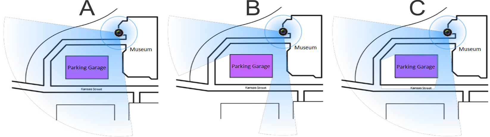
Example Configuration A Block field of view is not selected for the rectangle representing the parking garage. B Block field of view is selected for the rectangle representing the parking garage. C Block field of view is selected for the rectangle representing the parking garage and the Elevation is defined for both the parking garage and the camera. Tip:To test the coverage of all the cameras, click . -
In the Map designer toolbar, click Save
(
 ).
).